Ni multism how to add label at node
02/03/2011 · Learn how to make net names visible and how to rename them.
A Quick EE-331 Tutorial on Multisim Circuit Analysis R. B. Darling – Winter 2011 This is a quick step-by-step tutorial that can be followed to learn the basics of circuit simulation
Multisim offers multiple ways to analyze the circuit using virtual instruments. Some of the basic instruments needed for this lab are described below. 1) Multimeter Use the Multimeter to measure AC or DC voltage or current, and resistance or decibel loss between two nodes in a circuit. To use the Multimeter click on
I’m plotting data on a waveform chart or graph, and the X-Axis units are currently in the form of a timestamp. Instead, I would like to change the units of the X-Axis to seconds. How can I do this?
Note: This help applies to LabVIEW 2018. For other supported versions of the help, launch from product or download from this page.
Additional Information If you have purchased NI software, and but do not yet have your serial number because the shipped software kit has not arrived, there is an option to download and install a trial evaluation of most NI software. Once the software kit arrives, you can simply enter the serial number included into NI License Manager to permanently activate the release version.
Notes. A hashable object is one that can be used as a key in a Python dictionary. This includes strings, numbers, tuples of strings and numbers, etc.
02/03/2011 · Measure DC node voltage with a measurement probe. This feature is not available right now. Please try again later.
YouTube Embed: No video/playlist ID has been supplied
Change the X-Axis Units on a Waveform Graph or Chart to

Introduction to MultiSim – Part 1
If you need to make multiple connections at the same point you can add a Junction by going to Place-> Junction (Ctrl+J). You might be afraid that the connection has not been made since MultiSim does not really show a connection but as long as you click on the red dot that appears near the terminals the connection will be made. To connect a wire
On newer version of Windows, Multisim does not create a desktop icon. If you run into this issue, you can follow these instructions to pin Multisim to your taskbar and create a desktop shortcut: Go to your start menu and type “Multisim” Right-click the “Multisim 14.1” application and choose “Pin to Taskbar”.
The property nodes you would use to do this are: Caption.Visible, Label.Visible and Caption.Text, respectively. It is possible to write to the Label.Text property programatically from another VI when the VI is not running. For an example of this look at Changing Label Text of Control in Another VI.

09/08/2007 · Hi all,I am new to Labview and I want to ask how to add a script node (Matlab script) to a VI, since I can not find it in the function palette. Is that because it is not in base package? Do I need to install other packages?Thank you,Hannah
Displays the Set Y Value => on Crosshair_1 dialog box. The crosshair number depends on whether you selected Cursor 1 or Cursor 2.Enter the desired location on the y-axis to where you would like the cursor to move and click OK.The cursor moves to the right, to …
Solution The general Ground (GND) symbol cannot be assigned to another net, as it is considered universal for SPICE simulation purposes.Additional grounds can be used in a design by using DGND symbols. To do so, place a DGND in the net and set the RefDes to GND: . Select DGND (Master Database » Sources » POWER_SOURCES » DGND) in the component selector and place it in the desired net.
Multisim™ software integrates industry-standard SPICE simulation with an interactive schematic environment to instantly visualize and analyze electronic circuit behavior. Its intuitive interface helps educators reinforce circuit theory and improve retention of theory throughout engineering curriculum. By adding powerful circuit simulation and
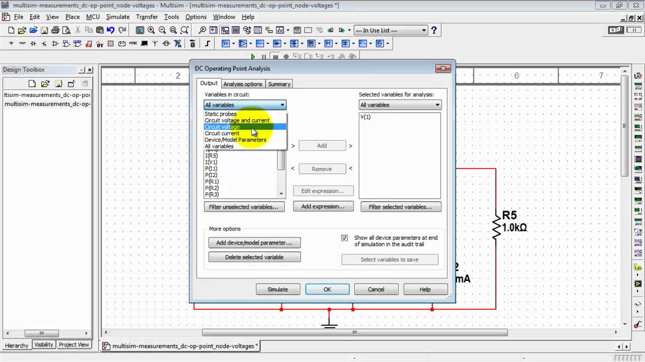
02/03/2011 · Find node voltages with a DC Operating Point analysis. Choosing a Backup Generator Plus 3 LEGAL House Connection Options – Transfer Switch and More – Duration: 12:39. Bailey Line Road Recommended
Tap a component’s wiring point (black diamond) and tap another component’s wiring point. The connection is automatically made, and the new wire is selected. Zoom in and pan as required while wiring. Connecting components pin-to-pin. Drag a component until the desired pin touches a pin on another component and release.
EE101 – Lab 3: Introduction to PSPICE/Multisim Prelab Exercises. Analyze the circuit below. Label each node in the circuit. (there are three, including ground) Determine the Req for the resistors in the circuit. Find the source current through the circuit. Find the voltage at each node. (that is, the voltage drop between that node and gound).
8. Step 7: Map Symbol Pins to the Model Nodes. You must map the symbol pins to the SPICE model nodes in order for Multisim to correctly simulate the component. For all subcircuit or macro models, the model nodes are typically documented in the header text of the SPICE model. There is also a line that declares that the model is a subcircuit model and lists the model name followed by the model nodes …

12/12/2003 · To that, I would ask whether there might possibly be in the works a way to display .op voltages of pre-selected nodes? Would be real handy to have expected voltages on the schematic when I pass the printout over to
Add label to existing node with Cypher. Ask Question Asked 5 years, 9 months ago. Active 3 years, 3 months ago. Viewed 22k times 38. 5. How can I add a label to an existing node using a Cypher query?
Therefore, if R1 = R2, then the gain is equal to 2, which you will verify when you run interactive simulation in Multisim. Figure 1. Non-inverting amplifier circuit. Back to Top. 2. Part A: Selecting Components. Begin by drawing your schematic in the Multisim environment.
13/04/2011 · Place and configure the AC voltage source, a sinusoidal source suitable for interactive simulation, transient analysis, and AC (frequency sweep) analysis.
draw_networkx_labels Draw node labels on the graph G. Parameters: G (graph) – A networkx graph; pos (dictionary) – A dictionary with nodes as keys and positions as values. Positions should be sequences of length 2. labels (dictionary, optional (default=None)) – Node labels in a dictionary keyed by node of text labels; font_size – Font size for text labels (default=12) font_color
02/03/2011 · Multisim measurement probes normally display “node voltage,” the voltage of a node with respect to ground. Learn how to reference one probe to another so that it …
06/07/2009 · There is a function label in multisim, but it changed the netname of the wire. (CTRL + I) or (Place –> Connectors –> HB / SC Connector) I would like that …
Included software: LabVIEW NXG, LabVIEW FPGA Module, LabVIEW Real-Time Module only for NI Linux Real-Time, LabVIEW MathScript RT Module, Modulation Toolkit, supported hardware drivers, visual hardware configuration and navigation tools, floating-point to fixed-point conversion utility, and multirate digital signal processing nodes
NI Multisim AC voltage source YouTube
Tutorial on how to create and simulate a circuit online; then, learn how to create a group and share circuits with others.
Introduction to MultiSim – Part 1 Prepared by: Mohamad Eid Summer 2007 The purpose of this document is to introduce the many features of MultiSim.
Labels And Colors¶ [source code]#!/usr/bin/env python “”” Draw a graph with matplotlib, color by degree. You must have matplotlib for this to work. “”” __author__ – brother p touch pt d210 label maker instructions Documentation Conventions When Multisim guides refer to a toolbar button, an image of the button appears in the left column. Multisim guides use the convention Menu/Item to indicate menu commands. For example,“File/Open” means choose the Open command from the File menu. Multisim guides use the convention of an arrow ( ) to indicate the start of procedural information.
The National Instruments Multisim MCU Module adds microcontroller unit cosimulation capabilities to NI Multisim, so you can include a microcontroller, programmed in assembly or C code, within your SPICE-modeled circuit.The NI Multisim MCU Module works with Intel/Atmel 8051/8052 and Microchip PIC16F84A chips as well as a broad range of advanced peripherals such as external RAM and ROM, keyp
The Logic Converter can perform several transformations of a digital circuit representation or digital signal. This is a useful tool for digital circuit analysis, but has no real-world counterpart. It can be attached to a digital circuit to derive the truth table or Boolean expression the circuit represents, or it can produce a circuit from a truth table or Boolean expression.
Get help on how to use our online circuit design and simulation tools as well as information on how specific circuit components are modeled and simulated.
The Multisim schematic includes all the necessary connectors for the various input/output pins. On the other hand the Ultiboard file includes the board outline and footprints of the connectors placed at specific coordinates. Save both the Multisim and Ultiboard files using the same name. Capture your custom circuitry in Multisim.
The Label node provides a target for a routing decision, and does not process the message that it handles in any way. Typically, a Label node connects to a subflow that processes each message in a specific way, and either ends in an output node or in another RouteToLabel node.
Why dont wires have an optional label associated with them. Style guides have use label long wires but wires have to be moved often during development, and the labels are not fixed to the wire. This should be maintained for us. Right click on wire and add label, with ability to lock label to wire source, wire midpoint or wire destination.
How can I customize the x-axis labels on my graph/chart so they appear vertically like those in the image below?
Multisim 14.2 Help You can place a data label, containing the X-axis and Y-axis values, at the point where a cursor crosses the selected trace, on either analog or digital graphs. Complete the following steps to place a data label on a trace:
Analog, digital, and power electronics are foundational throughout countless application areas. Help students to overcome the challenges of understanding complex theoretical topics by implementing engaging hands-on labs that connect theory, to real-world experimentation.
Basically what I want to do is to add labels to the nodes but I don’t find the way to add them in this type of graphs. I tried using: nx.draw_networkx_labels(G,labels=labels,pos=nx.spring_layout(G),font_size=16) but there is a problem with the position layout, it is not next/in each node.
Lab 5: Experimentations with Multisim The goal of this laboratory is to learn some useful features of the Multisim simulation software and to highlight some differences between the computations as they are done in class and the results of Multisim simulations and benchtop e xperiments.
Creating a design and Simulating a design contain a tutorial that introduces you to Multisim Live and its many functions using the circuit shown below (RC filter). After simulating a design, you can stream data to Measurements Live and compare the simulation with real-time measurements using the NI ELVIS III …
Multisim 14.2 Help The Function Generator is a voltage source that supplies sinusoidal, triangular or square waves. It provides a convenient and realistic way to supply stimulus signals to a circuit.
Lab 5 Experimentations with Multisim USC Viterbi
Parameters: nodes (iterable container) – A container of nodes (list, dict, set, etc.).OR A container of (node, attribute dict) tuples. Node attributes are updated using the attribute dict. attr (keyword arguments, optional (default= no attributes)) – Update attributes for all nodes in nodes.Node attributes specified in nodes as a tuple take precedence over attributes specified generally.
What is Multisim™? National Instruments
Function Generator Multisim Help – National Instruments
Solved labels in multisim NI Community – National

NI Multisim Measure voltage with a referenced measurement
Link a Ground Symbol to a Custom Ground Net in Multism NI


NI Multisim MCU Module National Instruments
https://en.wikipedia.org/wiki/Node_Module
Context Menu from a Graph Cursor Multisim Help
– A Quick EE-331 Tutorial on Multisim Circuit Analysis
Archived Multisim User Guide National Instruments


NI Multisim Find node voltages with DC Operating Point
YouTube Embed: No video/playlist ID has been supplied
Tutorial NI Multisim Live
Get help on how to use our online circuit design and simulation tools as well as information on how specific circuit components are modeled and simulated.
NI Multisim Display and change net names YouTube
What is Multisim™? National Instruments
Displays the Set Y Value => on Crosshair_1 dialog box. The crosshair number depends on whether you selected Cursor 1 or Cursor 2.Enter the desired location on the y-axis to where you would like the cursor to move and click OK.The cursor moves to the right, to …
Multisim Templates for Custom Arduino Shields National
Additional Information If you have purchased NI software, and but do not yet have your serial number because the shipped software kit has not arrived, there is an option to download and install a trial evaluation of most NI software. Once the software kit arrives, you can simply enter the serial number included into NI License Manager to permanently activate the release version.
What is Multisim™? National Instruments
02/03/2011 · Find node voltages with a DC Operating Point analysis. Choosing a Backup Generator Plus 3 LEGAL House Connection Options – Transfer Switch and More – Duration: 12:39. Bailey Line Road Recommended
Link a Ground Symbol to a Custom Ground Net in Multism NI
Therefore, if R1 = R2, then the gain is equal to 2, which you will verify when you run interactive simulation in Multisim. Figure 1. Non-inverting amplifier circuit. Back to Top. 2. Part A: Selecting Components. Begin by drawing your schematic in the Multisim environment.
NI Multisim Find node voltages with DC Operating Point
Change the X-Axis Units on a Waveform Graph or Chart to
02/03/2011 · Learn how to make net names visible and how to rename them.
LabVIEW 2018 Help National Instruments – zone.ni.com
How Can I Customize the X-Axis Labels on My LabVIEW Graph
How to add labels to nodes in a CIRCULAR GRAPH with
02/03/2011 · Multisim measurement probes normally display “node voltage,” the voltage of a node with respect to ground. Learn how to reference one probe to another so that it …
Multisim Tutorial Instrumentation LAB
Programmatically Changing the Label for a Control or NI
MULTISIM TUTORIAL ece.mtu.edu
13/04/2011 · Place and configure the AC voltage source, a sinusoidal source suitable for interactive simulation, transient analysis, and AC (frequency sweep) analysis.
National Instruments Engineering Teaching Resources
What is Multisim™? National Instruments
NI Multisim Find node voltages with DC Operating Point
Multisim™ software integrates industry-standard SPICE simulation with an interactive schematic environment to instantly visualize and analyze electronic circuit behavior. Its intuitive interface helps educators reinforce circuit theory and improve retention of theory throughout engineering curriculum. By adding powerful circuit simulation and
Wiring NI Multisim Live
National Instruments Engineering Teaching Resources
The National Instruments Multisim MCU Module adds microcontroller unit cosimulation capabilities to NI Multisim, so you can include a microcontroller, programmed in assembly or C code, within your SPICE-modeled circuit.The NI Multisim MCU Module works with Intel/Atmel 8051/8052 and Microchip PIC16F84A chips as well as a broad range of advanced peripherals such as external RAM and ROM, keyp
NI Multisim Measure DC node voltage with a measurement probe
Wiring NI Multisim Live
NI Multisim Display and change net names YouTube
06/07/2009 · There is a function label in multisim, but it changed the netname of the wire. (CTRL + I) or (Place –> Connectors –> HB / SC Connector) I would like that …
Finding the Serial Number of My National Instruments NI
Context Menu from a Graph Cursor Multisim Help
Labels And Colors — NetworkX 1.9 documentation
Displays the Set Y Value => on Crosshair_1 dialog box. The crosshair number depends on whether you selected Cursor 1 or Cursor 2.Enter the desired location on the y-axis to where you would like the cursor to move and click OK.The cursor moves to the right, to …
Data Labels Multisim Help – National Instruments – NI
The Multisim schematic includes all the necessary connectors for the various input/output pins. On the other hand the Ultiboard file includes the board outline and footprints of the connectors placed at specific coordinates. Save both the Multisim and Ultiboard files using the same name. Capture your custom circuitry in Multisim.
A Quick EE-331 Tutorial on Multisim Circuit Analysis
Measuring voltage difference NI Multisim Live
Programmatically Changing the Label for a Control or NI
How can I customize the x-axis labels on my graph/chart so they appear vertically like those in the image below?
add a scipt node NI Community – National Instruments
The National Instruments Multisim MCU Module adds microcontroller unit cosimulation capabilities to NI Multisim, so you can include a microcontroller, programmed in assembly or C code, within your SPICE-modeled circuit.The NI Multisim MCU Module works with Intel/Atmel 8051/8052 and Microchip PIC16F84A chips as well as a broad range of advanced peripherals such as external RAM and ROM, keyp
NI Multisim AC voltage source YouTube
National Instruments Engineering Teaching Resources
06/07/2009 · There is a function label in multisim, but it changed the netname of the wire. (CTRL + I) or (Place –> Connectors –> HB / SC Connector) I would like that …
Finding the Serial Number of My National Instruments NI
MULTISIM TUTORIAL ece.mtu.edu
Introduction to Multisim Learn to Capture ni.com
On newer version of Windows, Multisim does not create a desktop icon. If you run into this issue, you can follow these instructions to pin Multisim to your taskbar and create a desktop shortcut: Go to your start menu and type “Multisim” Right-click the “Multisim 14.1” application and choose “Pin to Taskbar”.
NI Multisim Find node voltages with DC Operating Point
NI Multisim Measure DC node voltage with a measurement probe
Note: This help applies to LabVIEW 2018. For other supported versions of the help, launch from product or download from this page.
MULTISIM TUTORIAL ece.mtu.edu
Tap a component’s wiring point (black diamond) and tap another component’s wiring point. The connection is automatically made, and the new wire is selected. Zoom in and pan as required while wiring. Connecting components pin-to-pin. Drag a component until the desired pin touches a pin on another component and release.
A Quick EE-331 Tutorial on Multisim Circuit Analysis
Multisim Templates for Custom Arduino Shields National